Du verwendest einen veralteten Browser. Es ist möglich, dass diese oder andere Websites nicht korrekt angezeigt werden.
Du solltest ein Upgrade durchführen oder einen alternativen Browser verwenden.
Du solltest ein Upgrade durchführen oder einen alternativen Browser verwenden.
1.0a4-Azurit
- Ersteller pfleger0815
- Erstellt am
One more question.
I downloaded azurit 1.0a4-Azurit and also last arduino programmer 1.6.7, but during compilation I have a lot of error :
any idea ?
update:
with arduino version 1.6.5 it's ok and uploaded, but still error in serial monitor :
Motor mow fault ? how he knows ? I'm using FET for mow motor.
Alex
I downloaded azurit 1.0a4-Azurit and also last arduino programmer 1.6.7, but during compilation I have a lot of error :
Code:
C:UsersxxxAppDataLocalTempbuilddc26d9afde90342664dd0ce09ea68f9a.tmpsketchunusedbehavior.cpp:25:19: fatal error: robot.h: No such file or directory

 #include "robot.h"

                   ^

compilation terminated.
any idea ?
update:
with arduino version 1.6.5 it's ok and uploaded, but still error in serial monitor :
Code:
SETUP
ADCMan: found calib data
---ADC calib---
ADC sampleRate=38462
AD0	min=9999	max=-9999	diff=-19998	ofs=0
AD1	min=9999	max=-9999	diff=-19998	ofs=0
AD2	min=9999	max=-9999	diff=-19998	ofs=0
AD3	min=9999	max=-9999	diff=-19998	ofs=545
AD4	min=9999	max=-9999	diff=-19998	ofs=392
AD5	min=9999	max=-9999	diff=-19998	ofs=510
AD6	min=9999	max=-9999	diff=-19998	ofs=0
AD7	min=9999	max=-9999	diff=-19998	ofs=0
AD8	min=9999	max=-9999	diff=-19998	ofs=0
AD9	min=9999	max=-9999	diff=-19998	ofs=511
AD10	min=9999	max=-9999	diff=-19998	ofs=0
AD11	min=9999	max=-9999	diff=-19998	ofs=0
AD12	min=9999	max=-9999	diff=-19998	ofs=0
AD13	min=9999	max=-9999	diff=-19998	ofs=0
AD14	min=9999	max=-9999	diff=-19998	ofs=0
AD15	min=9999	max=-9999	diff=-19998	ofs=0
matchSignal size=24
subSample=4
capture size=192
IMU error: no calib data
--------
accOfs=0.00,0.00,0.00
accScale=2.00,2.00,2.00
comOfs=0.00,0.00,0.00
comScale=2.00,2.00,2.00
--------
initL3G4200D
gyro read error
gyro read error
gyro read error
loadSaveErrorCounters: read
loadSaveErrorCounters addrstop=422
loadUserSettings
EEPROM USERDATA: NO EEPROM USER DATA
PLEASE CHECK AND SAVE YOUR SETTINGS
t     0 l  0 v0 ERR  spd    0    0    0 sen    0    0    0 bum    0    0 dro    0    0 son   0 yaw   0 pit   0 rol   0 bat  0.0 chg  0.0  0.0 imu  0 adc  0 Ardumower
loadSaveRobotStats: read
loadSaveRobotStats addrstop=822
t     0 l  0 v0 FORW spd   25   25    0 sen    0    0    0 bum    0    0 dro    0    0 son   0 yaw   0 pit   0 rol   0 bat  0.0 chg  0.0  0.0 imu  0 adc  0 Ardumower
START
Ardumower 1.0a4-Azurit
Config: Ardumower
press...
  d for menu
  v to change console output (sensor counters, values, perimeter etc.)
sen_counters
Error: motor mow fault
t     0 l  0 v0 ERR  spd    0    0    0 sen    0    0    0 bum    0    0 dro    0    0 son   0 yaw   0 pit   0 rol   0 bat  0.0 chg  0.0  0.0 imu  0 adc  0 Ardumower
Error: motor mow fault
DS1307 data1 error
RTC data error!
RTC date received: Sun 01.01.2013
t     0 l  0 v0 ERR  spd    0    0    0 sen    0    0    0 bum    0    0 dro    0    0 son   0 yaw   0 pit   0 rol   0 bat 25.8 chg  0.0  0.0 imu  0 adc  0 Ardumower
Error: motor mow fault
Error: motor mow fault
Error: motor mow fault
Error: motor mow fault
Error: motor mow fault
Error: motor mow fault
t     1 l  0 v0 ERR  spd    0    0    0 sen    0    0    0 bum    0    0 dro    0    0 son   0 yaw   0 pit   0 rol   0 bat 25.7 chg  0.0  0.0 imu  0 adc  3 Ardumower
Error: motor mow fault
Motor mow fault ? how he knows ? I'm using FET for mow motor.
Alex
Now compile is ok, but still motor mow error.
Here is my setup :
digital pins 6,7, and 8 aren't use in my PCB. Is it correct or what mean : if using MOSFET, keep unconnected ??
in error counters in pfodapp I see : motor mow 255, but no overload error.
What is quite strange is, that in pfodapp I can start mow motor manually, but I can not start motors, but motors I can start in "motor test" under serial monitor in Arduino SW.
Alex
Here is my setup :
Code:
#define pinMotorMowPWM 2           // M1_IN1 mower motor PWM pin (if using MOSFET, use this pin)
#define pinMotorMowDir 6           // M1_IN2 mower motor Dir pin (if using MOSFET, keep unconnected)
#define pinMotorMowSense A3        // M1_FB  mower motor current sense
#define pinMotorMowFault 8         // M1_SF  mower motor fault   (if using MOSFET/L298N, keep unconnected)
#define pinMotorMowEnable 7        // EN mower motor enable      (if using MOSFET/L298N, keep unconnected)
digital pins 6,7, and 8 aren't use in my PCB. Is it correct or what mean : if using MOSFET, keep unconnected ??
in error counters in pfodapp I see : motor mow 255, but no overload error.
What is quite strange is, that in pfodapp I can start mow motor manually, but I can not start motors, but motors I can start in "motor test" under serial monitor in Arduino SW.
Alex
It all depends on what kind of driver you use for the mow motor : m33926 (current standard), single mosfet driver (earlier version of ardumower) or another kind (like L298N or 6201P or ...). And you have to call the right driver in software. Just check in mower.cpp, last but one routine (setActuator).
is it this ? :
case ACT_MOTOR_MOW: setMC33926(pinMotorMowDir, pinMotorMowPWM, value); break;// Motortreiber einstellung - bei Bedarf ändern z.B setL298N auf setMC33926
but I'm using previous version with MOSFET as described in setup :
#define pinMotorMowPWM 2 // M1_IN1 mower motor PWM pin (if using MOSFET, use this pin)
#define pinMotorMowDir 6 // M1_IN2 mower motor Dir pin (if using MOSFET, keep unconnected)
#define pinMotorMowSense A3 // M1_FB mower motor current sense
#define pinMotorMowFault 8 // M1_SF mower motor fault (if using MOSFET/L298N, keep unconnected)
#define pinMotorMowEnable 7 // EN mower motor enable (if using MOSFET/L298N, keep unconnected)
#define pinMotorMowRpm 18
Alex
case ACT_MOTOR_MOW: setMC33926(pinMotorMowDir, pinMotorMowPWM, value); break;// Motortreiber einstellung - bei Bedarf ändern z.B setL298N auf setMC33926
but I'm using previous version with MOSFET as described in setup :
#define pinMotorMowPWM 2 // M1_IN1 mower motor PWM pin (if using MOSFET, use this pin)
#define pinMotorMowDir 6 // M1_IN2 mower motor Dir pin (if using MOSFET, keep unconnected)
#define pinMotorMowSense A3 // M1_FB mower motor current sense
#define pinMotorMowFault 8 // M1_SF mower motor fault (if using MOSFET/L298N, keep unconnected)
#define pinMotorMowEnable 7 // EN mower motor enable (if using MOSFET/L298N, keep unconnected)
#define pinMotorMowRpm 18
Alex
Yes it is. You have to include (in driver.cpp) the following routine and the corresponding header (in driver.h)
// MOS-FET motor driver
void setMOSFET(int pinPWM, int speed) {
if (speed > 10) {
analogWrite(pinPWM, ((byte)abs(speed)));
} else {
analogWrite(pinPWM, ((byte)0));
}
}
and replace the call to setMC33926(...) by setMOSFET(pinMotorMowDir, value);
Jacques
// MOS-FET motor driver
void setMOSFET(int pinPWM, int speed) {
if (speed > 10) {
analogWrite(pinPWM, ((byte)abs(speed)));
} else {
analogWrite(pinPWM, ((byte)0));
}
}
and replace the call to setMC33926(...) by setMOSFET(pinMotorMowDir, value);
Jacques
I checked very old versions where was only MOSFET used for mow motor and L298N for motors and here was used driver L298N for all and no errors.
It must be a software bug in last revision with fault signal from MC33926 which is from MOSFET missing.
Mow error will start immediately after mower start ( can hear a beep signals ).
Alex
update :
mower.cpp :
if (digitalRead(pinMotorMowFault)==LOW){
robot.addErrorCounter(ERR_MOTOR_MOW);
Console.println(F("Error: motor mow fault"));
robot.setNextState(STATE_ERROR, 0);
//digitalWrite(pinMotorMowEnable, LOW);
//digitalWrite(pinMotorMowEnable, HIGH);
}
so when this pin isn't connected, error must be here.
It's SW bug.
It must be a software bug in last revision with fault signal from MC33926 which is from MOSFET missing.
Mow error will start immediately after mower start ( can hear a beep signals ).
Alex
update :
mower.cpp :
if (digitalRead(pinMotorMowFault)==LOW){
robot.addErrorCounter(ERR_MOTOR_MOW);
Console.println(F("Error: motor mow fault"));
robot.setNextState(STATE_ERROR, 0);
//digitalWrite(pinMotorMowEnable, LOW);
//digitalWrite(pinMotorMowEnable, HIGH);
}
so when this pin isn't connected, error must be here.
It's SW bug.

Hi Alexander,
Thank you for your answer. Unfortunately no oscilloscope, but I implemented other type of encoder - no HAL and neodine magnet. Now I have optical encoder. Depends on this I have one question - is somewhere defined in the SW which type / precise encoder I'm using? If I will use HAL, I have 1 pulse/cycle, but with this new one I have 400pulses/cycle. Same question is for odometry.
Thank you
Alex
Thank you for your answer. Unfortunately no oscilloscope, but I implemented other type of encoder - no HAL and neodine magnet. Now I have optical encoder. Depends on this I have one question - is somewhere defined in the SW which type / precise encoder I'm using? If I will use HAL, I have 1 pulse/cycle, but with this new one I have 400pulses/cycle. Same question is for odometry.
Thank you
Alex
AlexanderG schrieb:Hi Alex,
You seem to have done everything correctly - can you measure the pin using an oscilloscope just to make sure you have a valid signal there?
Keep up the good work!
Regards,
Alexander
Alexander, I need your help regarding rpm measuremet of mow motor. Tomorrow I will do a oscilloscope measurement, but one more question to SW configuration. Is necessary somehow change this, if I have a signal on analog pin number 10 ? :
Code:
// enable interrupts
  #ifdef __AVR__
    // R/C
    PCICR |= (1<<PCIE0);
    PCMSK0 |= (1<<PCINT4);
    PCMSK0 |= (1<<PCINT5);
    PCMSK0 |= (1<<PCINT6);
    PCMSK0 |= (1<<PCINT1);

    // odometry
    PCICR |= (1<<PCIE2);
    PCMSK2 |= (1<<PCINT20);
    PCMSK2 |= (1<<PCINT21);
    PCMSK2 |= (1<<PCINT22);
    PCMSK2 |= (1<<PCINT23);

    // mower motor speed sensor interrupt
    //attachInterrupt(5, rpm_interrupt, CHANGE);
    PCMSK2 |= (1<<PCINT19);
  #else
    // Due interrupts
    attachInterrupt(pinOdometryLeft, PCINT2_vect, CHANGE);
    attachInterrupt(pinOdometryLeft2, PCINT2_vect, CHANGE);
    attachInterrupt(pinOdometryRight, PCINT2_vect, CHANGE);
    attachInterrupt(pinOdometryRight2, PCINT2_vect, CHANGE);

    attachInterrupt(pinRemoteSpeed, PCINT0_vect, CHANGE);
    attachInterrupt(pinRemoteSteer, PCINT0_vect, CHANGE);
    attachInterrupt(pinRemoteMow, PCINT0_vect, CHANGE);
    attachInterrupt(pinRemoteSwitch, PCINT0_vect, CHANGE);

    //attachInterrupt(pinMotorMowRpm, rpm_interrupt, CHANGE);
    attachInterrupt(pinMotorMowRpm, PCINT2_vect, CHANGE);
  #endif
please can you explain me this code ?
Thank you
Alex
Zuletzt bearbeitet von einem Moderator:
Hello Alex,
Let's explain how it works for one digital pin. Let's assume you want to use Mega2560 digital pin 10. According to Arduino Mega schematics:
1. Arduino Pin named "10" is actually Mega 2560 chip Pin named "PK2".
2. Mega 2560 chip Pin "PK2" uses interrupt line "PCINT18".
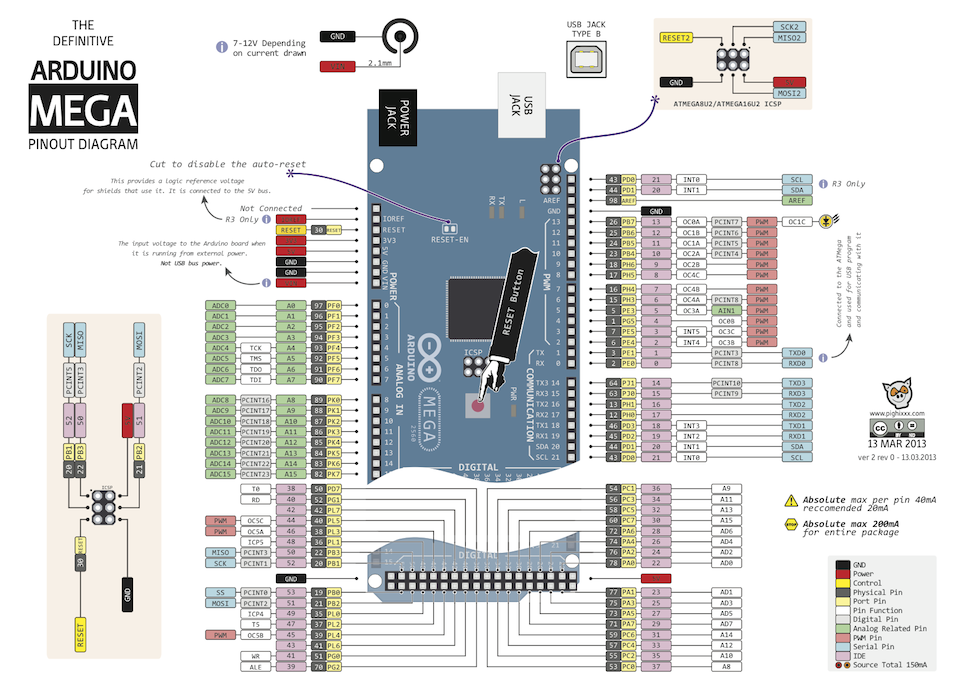
3. Now let's open Mega 2560 chip datasheet: http://www.atmel.com/images/atmel-2...r-atmega640-1280-1281-2560-2561_datasheet.pdf
4. At page 113, you can see that PCINT18 is controlled via PCMSK2 register. If you want to use PCINT18 interrupt line, you have to enable that bit in the PCMSK2 register:
Now PCINT18 will trigger when Mega2560 pin "PK2" changes. But only if PCIE2 bit is set in the PCICR register (read the text in section 15.2.7 in the datasheet):
Now when the interrupts happens (digital pin changes), the CPU will stop, and jump into the interrupt function PCINT2 (and after executing the interrupt function it jumps back where it was running):
You only need to modify chip registers for PCINT0, PCINT1, PCINT2 - For pins that have normal INT (see Arduino Mega pinout), you can use Arduino 'attachInterrupt' function. See Arduino page for that Arduino function.
Regards,
Alexander
Attachment: https://forum.ardumower.de/data/media/kunena/attachments/905/ardunio_mega_pinout.png/
Let's explain how it works for one digital pin. Let's assume you want to use Mega2560 digital pin 10. According to Arduino Mega schematics:
1. Arduino Pin named "10" is actually Mega 2560 chip Pin named "PK2".
2. Mega 2560 chip Pin "PK2" uses interrupt line "PCINT18".
3. Now let's open Mega 2560 chip datasheet: http://www.atmel.com/images/atmel-2...r-atmega640-1280-1281-2560-2561_datasheet.pdf
4. At page 113, you can see that PCINT18 is controlled via PCMSK2 register. If you want to use PCINT18 interrupt line, you have to enable that bit in the PCMSK2 register:
Code:
PCMSK2 |= (1<<PCINT18);Now PCINT18 will trigger when Mega2560 pin "PK2" changes. But only if PCIE2 bit is set in the PCICR register (read the text in section 15.2.7 in the datasheet):
Code:
PCICR |= (1<<PCIE2);Now when the interrupts happens (digital pin changes), the CPU will stop, and jump into the interrupt function PCINT2 (and after executing the interrupt function it jumps back where it was running):
Code:
// interrupt function for PCINT2
ISR(PCINT2_vect, ISR_NOBLOCK){
  ... interrupt code ...
}
You only need to modify chip registers for PCINT0, PCINT1, PCINT2 - For pins that have normal INT (see Arduino Mega pinout), you can use Arduino 'attachInterrupt' function. See Arduino page for that Arduino function.
Regards,
Alexander
Attachment: https://forum.ardumower.de/data/media/kunena/attachments/905/ardunio_mega_pinout.png/
Zuletzt bearbeitet von einem Moderator:
Yes, exactly. The interrupt function is called for both signal changes (HIGH->LOW and LOW->HIGH). In that interrupt function you can read the state and then increase a counter like this (btw: never call some time consuming functions in an interrupt function):
In the Ardumower code this is working similar. Interrupt function reads digital pin state and calls robot.setMotorMowRPMState(state) with that state which itself increases 'motorMowRpmCounter'.
Code:
volatile unsigned long counter = 0;

ISR(PCINT2_vect, ISR_NOBLOCK){
  if (digitalRead(10) == HIGH) counter++;
}

void loop(){
  Serial.println(counter);
  delay(1000);
}
In the Ardumower code this is working similar. Interrupt function reads digital pin state and calls robot.setMotorMowRPMState(state) with that state which itself increases 'motorMowRpmCounter'.