Du verwendest einen veralteten Browser. Es ist möglich, dass diese oder andere Websites nicht korrekt angezeigt werden.
Du solltest ein Upgrade durchführen oder einen alternativen Browser verwenden.
Du solltest ein Upgrade durchführen oder einen alternativen Browser verwenden.
Valify - my robot lawnmower project
- Ersteller raess
- Erstellt am
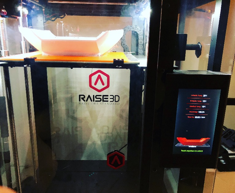
My printer had no tasks in the pipeline for tonight, So I 3D printed the mounting bracket for the scanse sweep.
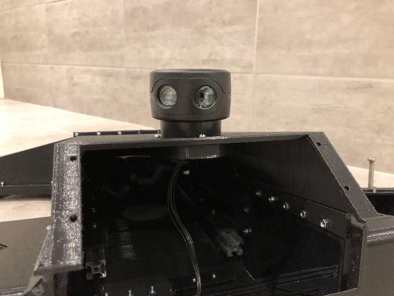
Read full post here: http://valify.se/2018/03/24/scanse-sweep-3d-printed-mounting-bracket/
First test run: https://www.youtube.com/watch?v=k9m85NCLcu4 Attachment: https://forum.ardumower.de/data/media/kunena/attachments/4372/IMG_2507.jpg/
Read full post here: http://valify.se/2018/03/24/scanse-sweep-3d-printed-mounting-bracket/
First test run: https://www.youtube.com/watch?v=k9m85NCLcu4 Attachment: https://forum.ardumower.de/data/media/kunena/attachments/4372/IMG_2507.jpg/
Zuletzt bearbeitet von einem Moderator:
Today I received my touchscreen for the robot. Did a quick and dirty prototype of the mouting bracket and printed it.
Here is how how it looks mounted on the robot. (Did not have 90-degree HDMI connectors at home, thats why is lifted when powered on).
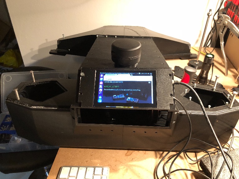
Read full post here: http://valify.se/2018/03/26/capacitive-touchscreen-running/ Attachment: https://forum.ardumower.de/data/media/kunena/attachments/4372/IMG_2572.jpg/
Here is how how it looks mounted on the robot. (Did not have 90-degree HDMI connectors at home, thats why is lifted when powered on).
Read full post here: http://valify.se/2018/03/26/capacitive-touchscreen-running/ Attachment: https://forum.ardumower.de/data/media/kunena/attachments/4372/IMG_2572.jpg/
Zuletzt bearbeitet von einem Moderator:
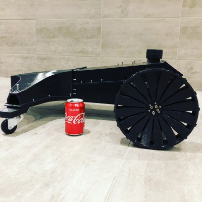
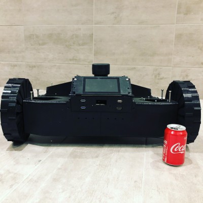
The appearance grows part by part. The Wheels made a huge difference on the size and the contours of the body.
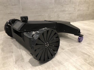
Follow and get the latest news on the build at http://valify.se Attachment: https://forum.ardumower.de/data/media/kunena/attachments/4372/1.jpg/
Follow and get the latest news on the build at http://valify.se Attachment: https://forum.ardumower.de/data/media/kunena/attachments/4372/1.jpg/
Zuletzt bearbeitet von einem Moderator:
@bernard I have been working on the pulley system a bit. And have some suggestions. Please note that I am new to belt system so please correct me if i am wrong.
Here is this first example. Running 4 pulleys. Motor pulley -> to an pulley with two belt positions (dimensions) 55mm and 15mm. The motor drives the 55mm pulley and the small pulley 15mm pulley drives the fourth pulley on the motor shaft 100mm
here is an sketch:
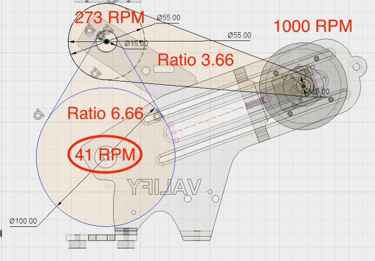
Here is a sketch with 3 pulley. Don't know how to calculate the ratio. Would this reduce the RPM also?
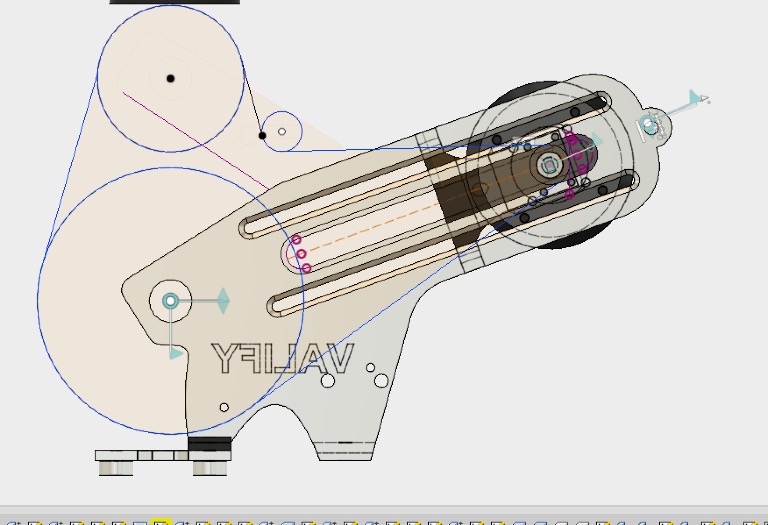
Would love to heat some feedback on this
Attachment: https://forum.ardumower.de/data/media/kunena/attachments/4372/d2.jpeg/
Here is this first example. Running 4 pulleys. Motor pulley -> to an pulley with two belt positions (dimensions) 55mm and 15mm. The motor drives the 55mm pulley and the small pulley 15mm pulley drives the fourth pulley on the motor shaft 100mm
here is an sketch:
Here is a sketch with 3 pulley. Don't know how to calculate the ratio. Would this reduce the RPM also?
Would love to heat some feedback on this
Attachment: https://forum.ardumower.de/data/media/kunena/attachments/4372/d2.jpeg/
Zuletzt bearbeitet von einem Moderator:
The second i am OK with Roland,no interrest.
The first solution is OK.
To have a perfect value can you tell us the teeth number
To know the ratio you need to simply use the number of teeth of the pulley (the big / the smal).
Maybe you need to make some test before with your actual (low ratio) config to know if the motor have enought torque to start the wheel with a load on it (for example simulate a slope).
You start at 1000 RPM on motor but what about the motor datasheet at this low speed.
I think at 41 Rpm you are fast.
For the (38 ticks) encodeurs, this ratio is OK.
I don't know exactly where you find the motor but maybe it's possible to find a gearbox.
Here for example on stepper the ratio can go over 100 so for 30RPM on Wheel it's 3000 on motor.
www.kde-motor.com/product/gearedsteppermotor/nema17Gearedsteppermotor.html
By.
The first solution is OK.
To have a perfect value can you tell us the teeth number
To know the ratio you need to simply use the number of teeth of the pulley (the big / the smal).
Maybe you need to make some test before with your actual (low ratio) config to know if the motor have enought torque to start the wheel with a load on it (for example simulate a slope).
You start at 1000 RPM on motor but what about the motor datasheet at this low speed.
I think at 41 Rpm you are fast.
For the (38 ticks) encodeurs, this ratio is OK.
I don't know exactly where you find the motor but maybe it's possible to find a gearbox.
Here for example on stepper the ratio can go over 100 so for 30RPM on Wheel it's 3000 on motor.
www.kde-motor.com/product/gearedsteppermotor/nema17Gearedsteppermotor.html
By.
Thanks for the feedback guys!
Lets go for the first solution then.
As I wrote earlier the motors can handle Low RPM with high torque. I get 1000 RPM @25% Duty. The Torque will not be a problem. I can't hold the motor in place at start from standstill at Duty =>18%. I have no data sheet on the motors.
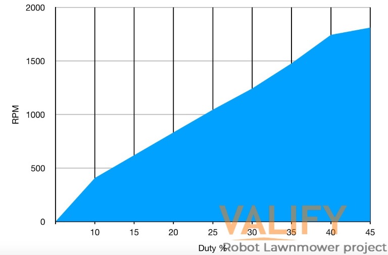
My Wheels are 230mm in diameter. Calculating wheel surface speed at you recommended 0.4m/s would give me 0.4*60/0.7225=33 RPM on the wheel shaft.
The Wheel surface speed at 41RPM would be around 0.5m/s. Why do you think this is to fast?
Why do you need teeth? The Pitch Diameter should be enough to calculate ratios?
For the tooth numbers. (I haven't the numbers for the 55mm diameter one yet).
12T -> 55mm Max diameter -> 12T-> 80T.
I am also changing the hall sensor to Magnetic Rotary Encoder allow up to 16384 positions per revolution. This would also improve my start from a stand still and increase the start torque slightly.
Attachment: https://forum.ardumower.de/data/media/kunena/attachments/4372/rpm-di.jpg/
Lets go for the first solution then.
As I wrote earlier the motors can handle Low RPM with high torque. I get 1000 RPM @25% Duty. The Torque will not be a problem. I can't hold the motor in place at start from standstill at Duty =>18%. I have no data sheet on the motors.
My Wheels are 230mm in diameter. Calculating wheel surface speed at you recommended 0.4m/s would give me 0.4*60/0.7225=33 RPM on the wheel shaft.
The Wheel surface speed at 41RPM would be around 0.5m/s. Why do you think this is to fast?
Why do you need teeth? The Pitch Diameter should be enough to calculate ratios?
For the tooth numbers. (I haven't the numbers for the 55mm diameter one yet).
12T -> 55mm Max diameter -> 12T-> 80T.
I am also changing the hall sensor to Magnetic Rotary Encoder allow up to 16384 positions per revolution. This would also improve my start from a stand still and increase the start torque slightly.
Attachment: https://forum.ardumower.de/data/media/kunena/attachments/4372/rpm-di.jpg/
Zuletzt bearbeitet von einem Moderator:
Hi.
If the motor can rotate at 50 RPM with torque and accurate sense control all is PERFECT.
Example : If you want to do a spirale mowing, one of the 2 Wheel need to rotate at 2 RPM with torque.
Here a cool link: https://forums.parallax.com/discussion/comment/1326585#Comment_1326585
Only test can confirm , but 0.5m/s max why not ?
Again congratulation for this very good work.
I am very impatient to see more.
What do you mean with low RPM?the motors can handle Low RPM with high torque
If the motor can rotate at 50 RPM with torque and accurate sense control all is PERFECT.
Example : If you want to do a spirale mowing, one of the 2 Wheel need to rotate at 2 RPM with torque.
Here a cool link: https://forums.parallax.com/discussion/comment/1326585#Comment_1326585
.Why do you think this is too fast?
Only test can confirm , but 0.5m/s max why not ?
Only because it's easier to compute but the diameter is also OK B) .Why do you need teeth?
From 38 to 16384 ????:dry: If it's work it's perfect.allow up to 16384 positions per revolution
Again congratulation for this very good work.
I am very impatient to see more.
Thanks Bernard
So I have started working with the encoders. In this case I will use a AS5048A. I also have the AS5047P, AS5047D and amt102V to test later on.
Printed the encoder mount:
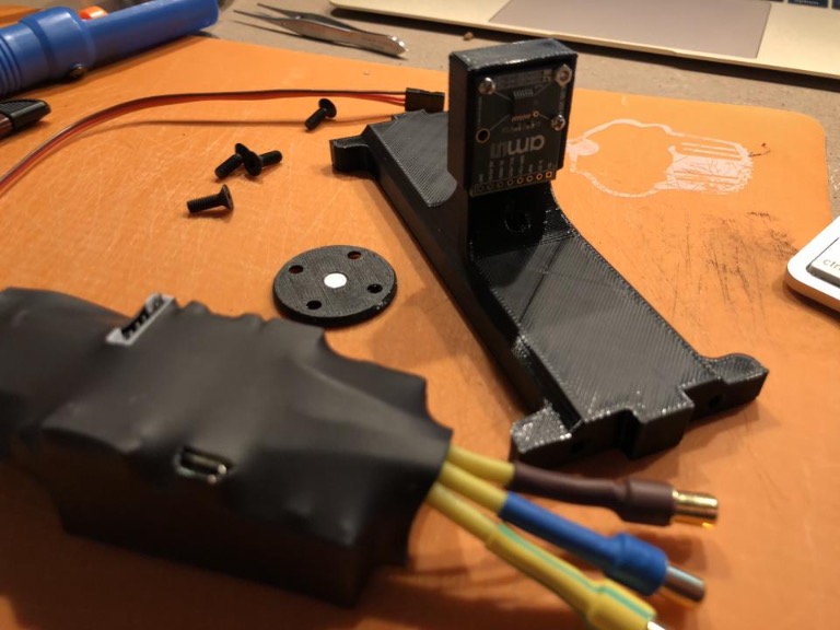
Still problem with noise. I think I need to get a shielded cable. Anyone got ideas about what cable I can use that I might have at home? I was thinking of an ethernet cable?
Video of the encoder test https://www.youtube.com/watch?v=R189nbmtxeU Attachment: https://forum.ardumower.de/data/media/kunena/attachments/4372/IMG_2675.jpg/
So I have started working with the encoders. In this case I will use a AS5048A. I also have the AS5047P, AS5047D and amt102V to test later on.
Printed the encoder mount:
Still problem with noise. I think I need to get a shielded cable. Anyone got ideas about what cable I can use that I might have at home? I was thinking of an ethernet cable?
Video of the encoder test https://www.youtube.com/watch?v=R189nbmtxeU Attachment: https://forum.ardumower.de/data/media/kunena/attachments/4372/IMG_2675.jpg/
Zuletzt bearbeitet von einem Moderator:
Hi.
Sorry for my English.
Again I don't think the main problem is the encoder
And be carrefull that to compute movement you need to count the ticks "relative", and not to know the absolute position of the Wheel the AS5048A is absolute ??
For the noise maybe the motor magnet disturb the coder magnet ??????????:blush:
I think if you get to find a bigger reduction ratio the 38 tick coder will work like a charm.
you need to use (i don't know exactly the name in English) but it's epicyclodal train.
If you can find a ratio=150 for example the 30 RPM on Wheel become 4500RPM on motor and 38 ticks become 5700 on Wheel and torque is *150 and it's solve all the question.
What is the fixation of motor NEMA or other??.
Sorry for my English.
Again I don't think the main problem is the encoder
And be carrefull that to compute movement you need to count the ticks "relative", and not to know the absolute position of the Wheel the AS5048A is absolute ??
For the noise maybe the motor magnet disturb the coder magnet ??????????:blush:
I think if you get to find a bigger reduction ratio the 38 tick coder will work like a charm.
you need to use (i don't know exactly the name in English) but it's epicyclodal train.
If you can find a ratio=150 for example the 30 RPM on Wheel become 4500RPM on motor and 38 ticks become 5700 on Wheel and torque is *150 and it's solve all the question.
What is the fixation of motor NEMA or other??.
So tested the AS5048A Encoder with a homemade shielded cable and it solved most problems. Encoder works but I could only read 180-360 degrees. Connected over SPI.
So I went ahead and tested a AS5047D and same problem here. I could only read 180-360 degrees. Connected over SPI. The AS5047D could also be connected as ABI. Tested ABI and that works. 0-360 degrees with 2000 steps per rev. Not as good as the AS5048A. But maybe it will suffice. I will also test a AS5047P and see how that works.
here is a small video on VESC position control
https://www.youtube.com/watch?v=VoYjUqWflZY
So I went ahead and tested a AS5047D and same problem here. I could only read 180-360 degrees. Connected over SPI. The AS5047D could also be connected as ABI. Tested ABI and that works. 0-360 degrees with 2000 steps per rev. Not as good as the AS5048A. But maybe it will suffice. I will also test a AS5047P and see how that works.
here is a small video on VESC position control
https://www.youtube.com/watch?v=VoYjUqWflZY
Hi.
Perfect, 2000 steps suffice because you have the ratio after it and the main is the Wheel position.
With this high value You can also put the encoder directly on the Wheel (maybe avoid noise on wire or magnet)
You only show the absolute position of the motor.
Did this test in relative mode work for example to move the mower 1 Meter forward :
Motor is stop.
Start with Accel Ramp.
Rotate for more than 100 * 360Deg (100Rev) and stop at 20 Deg for example
And stop with smooth brake if possible
Maybe ROS did it but ???
It's Strange that there is so many noise ?(IMU and Compass ???)
Perfect, 2000 steps suffice because you have the ratio after it and the main is the Wheel position.
With this high value You can also put the encoder directly on the Wheel (maybe avoid noise on wire or magnet)
You only show the absolute position of the motor.
Did this test in relative mode work for example to move the mower 1 Meter forward :
Motor is stop.
Start with Accel Ramp.
Rotate for more than 100 * 360Deg (100Rev) and stop at 20 Deg for example
And stop with smooth brake if possible
Maybe ROS did it but ???
It's Strange that there is so many noise ?(IMU and Compass ???)
The AS5047p Will have 4000 steps and Will proporly work as well. Mounting them on wheel is not I great idea? The encoder is needed in FOC mode on the VESC for rotar position. This help the brushless motors start at low speeds and with better torque. Mounting them the encoder on the wheel will not provide an absolute position of the rotor because of the gear ratio. I also have a couple of amt102v encoders (8000ticks) that I could mount on the wheels shaft. This way I can know the difference in degrees between motor and wheel shaft (an exact ratio)
What do you think?
Where do you see noise? On the video you see a differents in degrees between 250.85 and 251.2 degrees a max differents of 0.35degrees.
What do you think?
Where do you see noise? On the video you see a differents in degrees between 250.85 and 251.2 degrees a max differents of 0.35degrees.
Friday fun!
Testing the AS5048A encoder with 16384 positions per revolution and with the temporary drive system. Motor brackets are 3D printed and not perfect, therefore some annoying noises! Running VESC FOC Mode @10% Duty.
With the rotary position sensor I get a very smooth start and better torque. Before the start from standstill could be a little choppy and the sensor took care of this issue.
https://www.youtube.com/watch?v=h7JsRsa5fl8
Testing the AS5048A encoder with 16384 positions per revolution and with the temporary drive system. Motor brackets are 3D printed and not perfect, therefore some annoying noises! Running VESC FOC Mode @10% Duty.
With the rotary position sensor I get a very smooth start and better torque. Before the start from standstill could be a little choppy and the sensor took care of this issue.
https://www.youtube.com/watch?v=h7JsRsa5fl8
So time for an update again.
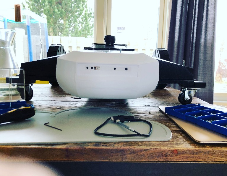
Printed mounting brackets for the front wheels (Please note that this is only test wheels before I make an effort the design some new ones with bearings etc.)
The brackets came out great. Following the contours of the body and blended in quite good. This parts was also printed with PETG.

Quick assembly with all wheel mounted.
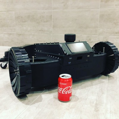
Testing the 3D printed front nose. Looks quite good. Minor adjustments needs to be done.
Printed with PrimaSelect PETG @240C, 85C bed, 3shells and 15% infill (Very solid outcome).
Countersink need to be adjusted to cut the body.
The Integrated ZR300 camera need some cover on the back.
Check if one can use a 90 degree USB instead of a normal USB head.
Attachment: https://forum.ardumower.de/data/media/kunena/attachments/4372/IMG_2878.jpg/
Printed mounting brackets for the front wheels (Please note that this is only test wheels before I make an effort the design some new ones with bearings etc.)
The brackets came out great. Following the contours of the body and blended in quite good. This parts was also printed with PETG.
Quick assembly with all wheel mounted.
Testing the 3D printed front nose. Looks quite good. Minor adjustments needs to be done.
Printed with PrimaSelect PETG @240C, 85C bed, 3shells and 15% infill (Very solid outcome).
Countersink need to be adjusted to cut the body.
The Integrated ZR300 camera need some cover on the back.
Check if one can use a 90 degree USB instead of a normal USB head.
Attachment: https://forum.ardumower.de/data/media/kunena/attachments/4372/IMG_2878.jpg/
Zuletzt bearbeitet von einem Moderator: