alterschwede
New member
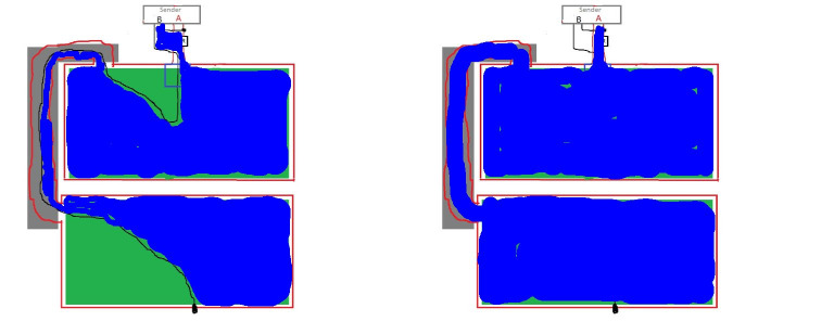
As I posted in a different thread concerning zone mowing, i am presently including a second perimeter wire B inside my outside wire B.
I am working on a solution, where the mower is able to identify which wire it has crossed and let it track wire A or B.
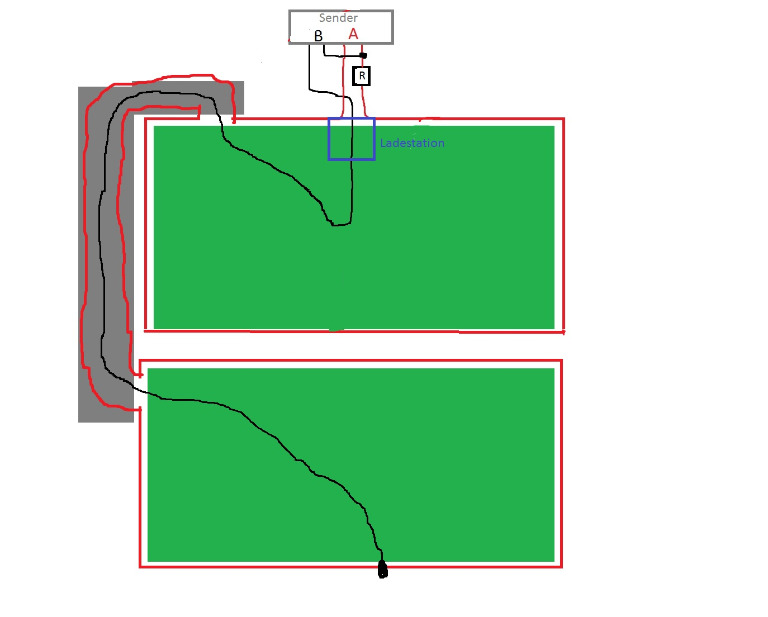
Both cables share a common Connection at the sender, since they are interconnected. But that means, that I have to periodically switch Signal A and B off ( 50 ms period). I am sending two different orthogonal codes via loop A and loop B. The mower calculates the correlation between those signals, and the greater MAG tells him, which loop is underneath / closest. Which is working very good so far. But the outside/inside recognition is my problem. I need a way, to let the receiver focus on Loop A or B and only update the MAG value A, when the Sender is transmitting on the loop A and vice versa. So the receiver needs to by synced to the sender and should change its focus phase correct every 50 ms.
My first thoughts are:
1. differentiate the MAG over time, where dMAG/dT is biggest/over specific Threshold, we found a Signal Change
2. sync a CTC Timer to this timestamp and let it overrun every 50 ms
3. change a Focus variable ( which MAG to be stored) inside the Timer ISR
continously: check if we are still synced
I am relative new to Timer coding and tried to learn as much as I could about it, but there might be some knowledge gaps.
my Questions are:
- if we let a Timer create an Interrupt every 50ms, will the Mega be able to handle it to all other tasks/interrupts?
- still a Timer left, perhaps all 5 Timer already needed
- is it possible to manually reset the TCNTn to zero at the time dMAG/dT is greatest
Does anybody see a chance that this could work, or perhabs a more simpler way in achieving the syncing?
Regards
Frederic
I am working on a solution, where the mower is able to identify which wire it has crossed and let it track wire A or B.
Both cables share a common Connection at the sender, since they are interconnected. But that means, that I have to periodically switch Signal A and B off ( 50 ms period). I am sending two different orthogonal codes via loop A and loop B. The mower calculates the correlation between those signals, and the greater MAG tells him, which loop is underneath / closest. Which is working very good so far. But the outside/inside recognition is my problem. I need a way, to let the receiver focus on Loop A or B and only update the MAG value A, when the Sender is transmitting on the loop A and vice versa. So the receiver needs to by synced to the sender and should change its focus phase correct every 50 ms.
My first thoughts are:
1. differentiate the MAG over time, where dMAG/dT is biggest/over specific Threshold, we found a Signal Change
2. sync a CTC Timer to this timestamp and let it overrun every 50 ms
3. change a Focus variable ( which MAG to be stored) inside the Timer ISR
continously: check if we are still synced
I am relative new to Timer coding and tried to learn as much as I could about it, but there might be some knowledge gaps.
my Questions are:
- if we let a Timer create an Interrupt every 50ms, will the Mega be able to handle it to all other tasks/interrupts?
- still a Timer left, perhaps all 5 Timer already needed
- is it possible to manually reset the TCNTn to zero at the time dMAG/dT is greatest
Does anybody see a chance that this could work, or perhabs a more simpler way in achieving the syncing?
Regards
Frederic